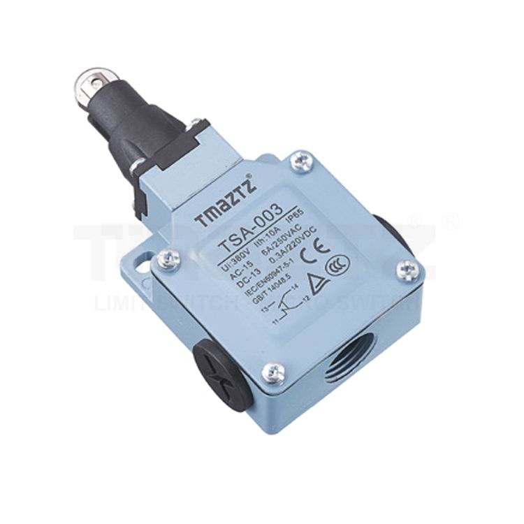
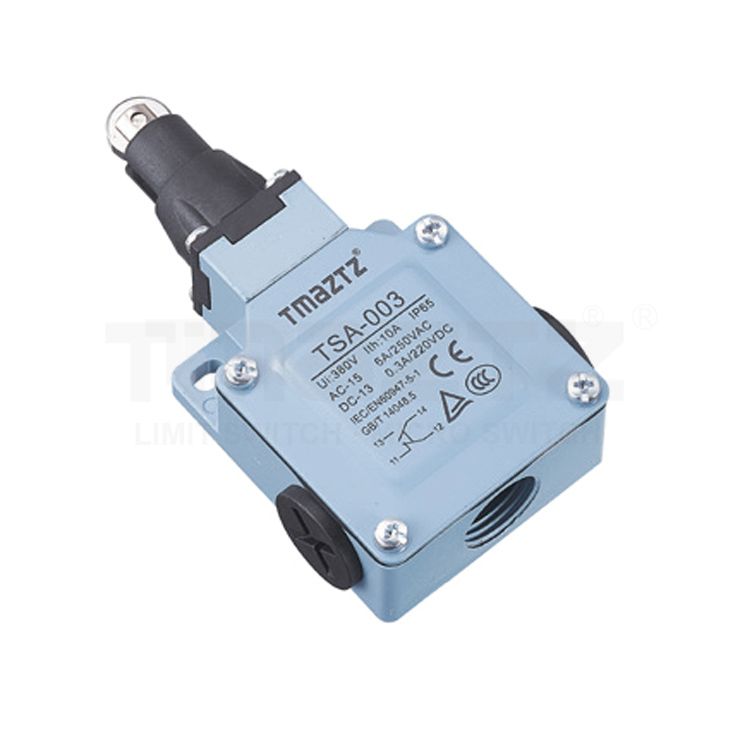
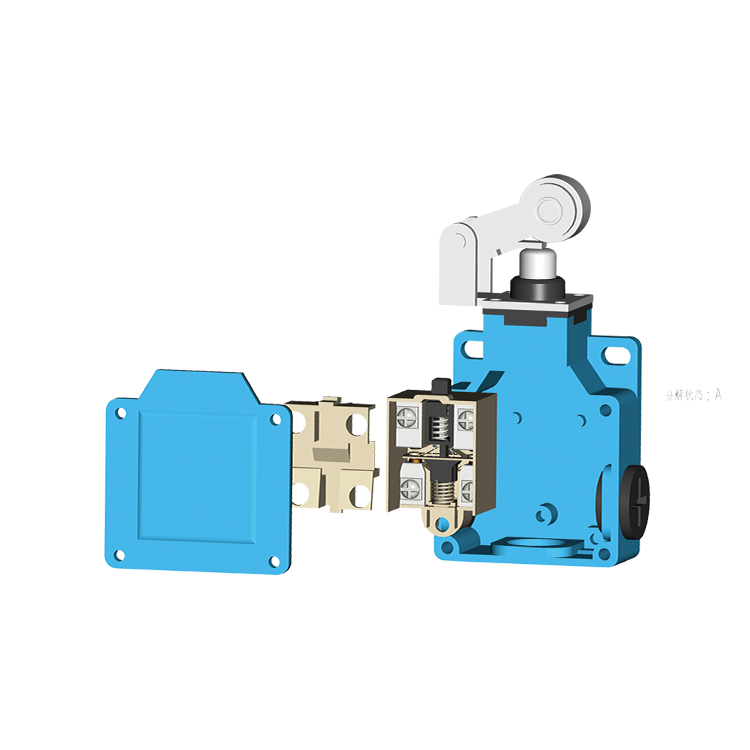
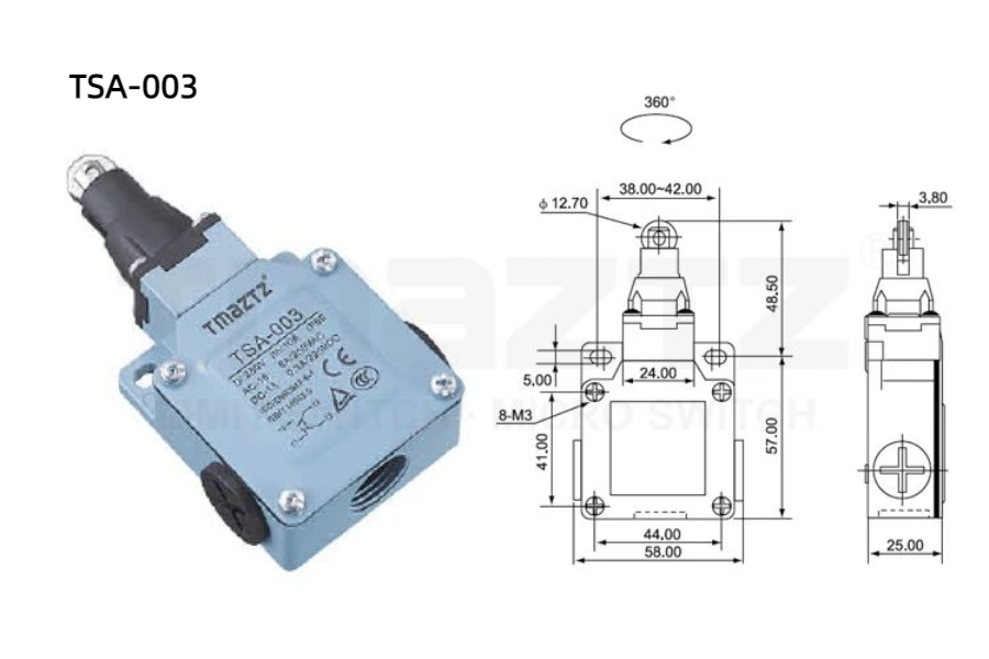
TSA-003 top-roller plunger actuator Limit Switch
1. Stainless steel idler wheel, punch and spring;
2. Selective M18x1.5 cable gland.
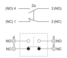
Contact Form:
 Product List
Technical Parameters
Top-roller Plunger Actuator Limit Switch Company---TMAZTZ
Ratings
| Rated voltage | Noninductive Load (A) | Inductive Load (A) | ||||||
| Resistance Load | Lamp Load | Inductive Load (A) | Motor Load | |||||
| NC | NO | NC | NO | NC | NO | NC | NO | |
| 125VAC | 5 | 5 | 1.5 | 0.7 | 3 | 3 | 2 | 1 |
| 250VAC | 5 | 5 | 1 | 0.5 | 3 | 3 | 1.5 | 0.8 |
| 8VDC | 5 | 5 | 3 | 3 | 5 | 4 | 3 | 3 |
| 14VDC | 5 | 5 | 3 | 3 | 4 | 4 | 3 | 3 |
| 30VDC | 5 | 5 | 3 | 3 | 4 | 4 | 3 | 3 |
| 125VDC | 0.4 | 0.4 | ||||||
| 250VDC | 0.2 | 0.2 | ||||||
| Inrush Current | N.C: below 24A, N.O: below 12A | |||||||
NOTE:
1. Inductive load has a power factor of 0.4 min.(AC) and a time constant of 7 msec.max.(DC).
2. Lamp load has an inrush current of 10 times the steady-state current,while motor load has an inrush current of 6 times the steady-state current.
3. Product with spring, its usable range of operating part is within one third of the whole spring length from the front end of spring.
TSA003 Limit Switch Instructions
1. Installation
Mounting: Choose a suitable location for mounting the switch, ensuring it aligns properly with the actuator or moving part.
Orientation: Install the switch in the recommended orientation (usually specified in the manual).
Secure Fastening: Use screws or brackets to securely attach the switch to the mounting surface.
2. Wiring
Power Supply: Ensure the power supply is off before making any electrical connections.
Connection: Connect the limit switch to the control circuit as per the wiring diagram provided in the manual.
Check Polarity: Ensure proper polarity if applicable, following the manufacturer's guidelines.
3. Setting the Actuation Point
Adjustment: If the switch has an adjustable actuator, position it to match the desired actuation point of the moving part.
Testing: Manually move the actuator to check if the limit switch activates at the correct position.
4. Testing the Switch
Power On: Once installed and wired, turn the power supply back on.
Function Test: Activate the mechanism to ensure the limit switch operates as intended, opening or closing the circuit when the actuator reaches the set point.
5. Maintenance
Regular Inspection: Periodically check the switch for wear, damage, or misalignment.
Clean Contacts: Ensure that the switch contacts are clean and free of debris for optimal performance.
Characteristics
| Operation speed | 0.5mm-50cm/sec |
| Operating frequency | Electical: 30 operations/minute |
| Contact resistance | 25mΩ max. (initial value) |
| Insulation resistance | 100mΩ min. (below 500VDC) |
| Dielectric Strength | 1000VAC, 50/60 Hz for 1 minute between terminals of the same polarity |
| 1500VAC, 50/60 Hz for 1 minute between current-carrying and non-current-carrying metal parts | |
| 1500VAC, 50/60 Hz for 1 minute between each terminal and ground | |
| Vibration | 10-55Hz,1.5mm double amplitude |
| Shock | Mechanical durable: 1, 000m/Sec2 (about 100G'S) Malfunction: 300m/Sec2 (about 30G'S) |
| Ambient Temperature | -10~+65℃ (With no icing) |
| Humidity | <95% RH |
| Weight | About 195 to 246g |
| Electrical Life | Above 500000 |
| Degree of protection | IP65 |
Operating Characteristics
| Operating Characteristics | Model | TSA-001 | TSA-003 | TSA-012 | TSA-021 | TSA-041 | TSA-031 | TSA-051 | TSA-061 | TSA-071 | TSA-081 |
| Operating force | OF (Max) | 7.84N | 7.84N | 7.84N | 3.92N | 3.92N | 3.92N | 3.92N | 1.47N | 1.47N | 1.47N |
| Release force | RF (Min) | 3.92N | 3.92N | 3.92N | 0.98N | 0.98N | 0.98N | 0.98N | 0.49N | 0.49N | 0.49N |
| Pre-travel | PT (Max) | 1.8mm | 1.8mm | 1.8mm | 20° | 20° | 20° | 20° | 30mm | 30mm | 30mm |
| Tripping position | TP±10% | 2.0mm | 2.0mm | 2.0mm | 22.5° | 22.5° | 22.5° | 22.5° | 22.5° | 22.5° | 22.5° |
| Movement differential | MD (Max) | 1.2mm | 1.2mm | 1.2mm | 10° | 10° | 10° | 10° | 14° | 14° | 14° |
| Over travel | OT (Min) | 4.0mm | 4.0mm | 4.0mm | 75° | 75° | 75° | 75° | 20mm | 20mm | 20mm |
| Total travel | TT (Min) | 5.8mm | 5.8mm | 5.8mm | 95° | 95° | 95° | 95° | 50mm | 50mm | 50mm |
| Rotary indexing | 22.5° | 22.5° | 22.5° | 22.5° |

